What is resistor
Resistor is an electrical device that resists the flow of electrical
current A current flowing through a resistance willcreate a voltage
drop across that resistance and convertselectrical energy directly
to heat.There are two types of resistors-fixed and variable.
A fixed resistor has a fixed value of ohms while a variableresistor
is adjustable.
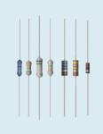
Fixed resistor

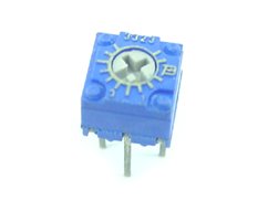
Variable resistor

Resister color code
.................................................................................................
Black = 0 , Brown = 1 , Red =2 , Orange = 3 , Yellow =4
Green = 5 , Blue = 6 , Violet = 7 , Gray = 8 , White=9
................................................................................................
Tolerance band
...............................................................................................
Brown = 1% , Red = 2% , Gold = 5% , Silver = 10% , None = 20%
..............................................................................................
How to read the resister color code

Values
= 1st Digit , 2st Digit , multiplier with “0” , % Tolerance
Example >> Brown - Red - Orange - Gold <<
Values = 12000 = 12KOhms Tolerance 5%
............................................................................. ...........................
Resister surface mout code
Same above but change color with number last digit
is the multiplier
Example
104 = 100K Ohms , 472 = 4.7K Ohms
........................................................................................................
Resister BS 1852 Coding
You will see in variable resistor
- The letter R is used for Ohms
- The letter K used for Kohms
- The letter M used for Megohms
and placed where the decimal point would go
.At the end is a letter that represents tolerance
Where M=20%, K=10%, J=5%,G=2%, and F=1%
Example
R33 = 0.33 ohms
4M7 = 4.7M ohms
47K3F = 47.3 K Ohms 1%
......................................................................................................
Standard Series Values Resister
1.0 , 10 , 100 , 1.0K , 10K , 100K , 1.0M , 10M
1.1 , 11 , 110 , 1.1K , 11K , 110K , 1.1M , 11M
1.2 , 12 , 120 , 1.2K , 12K , 120K , 1.2M , 12M
1.3 , 13 , 130 , 1.3K , 13K , 130K , 1.3M , 13M
1.5 , 15 , 150 , 1.5K , 15K , 150K , 1.5M , 15M
1.6 , 16 , 160 , 1.6K , 16K , 160K , 1.6M , 16M
1.8 , 18 , 180 , 1.8K , 18K , 180K , 1.8M , 18M
2.0 , 20 , 200 , 2.0K , 20K , 200K , 2.0M , 20M
2.2 , 22 , 220 , 2.2K , 22K , 220K , 2.2M , 22M
2.4 , 24 , 240 , 2.4K , 24K , 240K , 2.4M
2.7 , 27 , 270 , 2.7K , 27K , 270K , 2.7M
3.0 , 30 , 300 , 3.0K , 30K , 300K , 3.0M
3.3 , 33 , 330 , 3.3K , 33K , 330K , 3.3M
3.6 , 36 , 360 , 3.6K , 36K , 360K , 3.6M
3.9 , 39 , 390 , 3.9K , 39K , 390K , 3.9M
4.3 , 43 , 430 , 4.3K , 43K , 430K , 4.3M
4.7 , 47 , 470 , 4.7K , 47K , 470K , 4.7M
5.1 , 51 , 510 , 5.1K , 51K , 510K , 5.1M
5.6 , 56 , 560 , 5.6K , 56K , 560K , 5.6M
6.2 , 62 , 620 , 6.2K , 62K , 620K , 6.2M
6.8 , 68 , 680 , 6.8K , 68K , 680K , 6.8M
7.5 , 75 , 750 , 7.5K , 75K , 750K , 7.5M
8.2 , 82 , 820 , 8.2K , 82K , 820K , 8.2M
9.1 , 91 , 910 , 9.1K , 91K , 910K , 9.1M
.......................................................................................