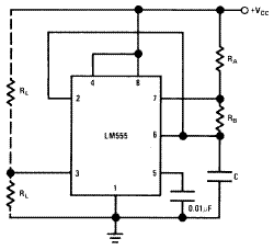
PWM generator circuit
A simple PWM (Pulse width modulation) generator circuit is
LM555 In ASTABLE OPERATION

ASTABLE OPERATION
Form circuit it will trigger itself and free run as a multivibrator.
The external capacitor charges through RA + RB and discharges
through RB. Thus the duty cycle may be precisely
set by the ratio of these two resistors.
In this mode of operation, the capacitor charges and discharges
between 1/3 VCC and 2/3 VCC. As in the triggered
mode, the charge and discharge times, and therefore the frequencyare
independent of the supply voltage.

- Top Trace: Output 5V/Div
- Bottom Trace: Capacitor Voltage 1V/Div.
The charge time (output high) is given by:
t1 = 0.693 (RA + RB) C
And the discharge time (output low) by:
t2 = 0.693 (RB) C
Thus the total period is:
T = t1 + t2 = 0.693 (RA +2RB) C
The frequency of oscillation is:
F = 1/T
The duty cycle is:
D = Rb/(Ra+2Rb)
Labels: PWM


<< Home