Electronic Device And Electronic Circuit

Data of electronic device , PCB Design and electronic circuit

Google
 
Web basicelectronic.blogspot.com

Thursday, August 24, 2006

Inductance Transducer Type

Passive Transducers is require external power
- Magnetic circuit transducer
operation = self inductance or mutual inductance of ac-excited coil is
varied by change in the magnetic circuit
- Reluctance pickup
operation = reluctance of the magnetic circuit is varied by change the
position of the iron core of a coil
- Differential Transformer
operation = the differnential voltage of two secondary winding of a
transformer is varied by positioning the magnetic core through an
external applied force
- Eddy current gage
operation = Inductance of a coil is varied by the proximity of an eddy
current plate
- Magnetostriction gage
operation = Magnetic properties are varied by pressure and stress
Capacitance Transducer Type

Passive Transducers is require external power
- variable capacitance pressure gage
operation = distance between two parallel plates is varies by an external
applied force
- capacitor microphone
operation = sound pressure varies the capacitance between a fix plate and
a movable diaphragm
- dielectric gage
operation = variation in capacitance by changes in the dielectric

Wednesday, August 23, 2006

Transducer Type

Passive Transducers is require external power,producing a variation in
Some electrical parameter which can be measured as a voltage or
current variation.

Resistance Transducer Type
- potentionmetric
operation = position of slider by external force varies the resistance in a
potentiometer or bridge circuit
- resistance strain gage
operation = resistance of a wire or semiconductor is change by compression
due to external appile stress
- pirani gage
operation = resistance of a heating element is varied by convection colling of
gas
- thermometer
operation = resistance of pure metal wire with a large positive temperature
coefficient of resistance varies with temperature.
- thermistor
operation = resistance of certain metal oxides with negative temperature
coefficient of resistance varies with temperature.
- hygrometer
operation = resistance of a conductive strip change with moisture content
- photoconductive cell
operation = resistance of the cell as a circuit element varies with incident

Friday, August 18, 2006

Constant current source circuit

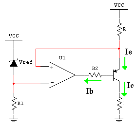
We can use a voltage reference turn into a Constant current source
circuit and use pnp-transistors for current-boosting


By op amp action ,the voltage across R is away Vref , give
Ie = Vref / R

Ie = Ib + Ic = (Ic/B) + Ic

Ic = [B/(B+1)] *Ie

Io = Ic = [B/(B+1)] * Vref / R about Vref / R
VL = Io*RL

Where maximum voltage of Vl(max) <>

We can adjust output current by adjust current setting resistance R

Wednesday, August 16, 2006

Extend current lm78xx regulator circuit

LM340/LM78XX Series
3-Terminal Positive Regulators
The LM140/LM340A/LM340/LM78XXC monolithic

3-terminal positive voltage regulators employ internal
current-limiting, thermal shutdown and safe-area compensation,
making them essentially indestructible. If adequate heat
sinking is provided, they can deliver over 1.0A output current.
They are intended as fixed voltage regulators in a wide
range of applications including local (on-card) regulation for
elimination of noise and distribution problems associated
with single-point regulation. In addition to use as fixed voltage
regulators, these devices can be used with external
components to obtain adjustable output voltages and currents.

Applications circuit of LM340/LM78XX Series

where
Io = Iq + Ireg
Iq = B *Ib
Ib = Ireg – Vbe/R1

Iq = B(Ireg – Vbe/R1)
Io = B*Ireg – B*Vbe/R1 + Ireg
Io = (B+1)*Ireg – B*Vbe/R1
R1*Io = R1 (B+1)*Ireg – B*Vbe

B*Vbe = R1[(B+1)*Ireg - Io]

R1 = B*Vbe / [(B+1)*Ireg - Io]


Example
We want to make regolater circuit 3 A
We choose current of regulater 0.6 A for safety
2N6133 for Q1
Io = 3A
Ireg = 0.6 A
Vbe = 1.4 V
B = 20

R1 = 20*1.4/[(20+1)*0.5 – 3]
R1 = 2.91

We choose R1 = 3 ohm

Tuesday, August 15, 2006

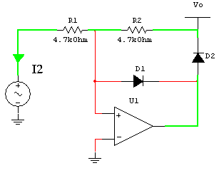
Half-wave precision rectifiers circuit

A half-wave rectifier is a circuit that passes only the positive or only the negative
Portion of a wave ,while blocking out the other portion
Rectifiers are impremented using diodes. The nonzero forward-voltage drop of
A pactical diode may cause intolerable errors in low-level signal

Proceeding of half-wave precision rectifiers circuit we separate are two case
Case 1 Vi > 0 negative input of op amp is higher positive input ,the op amp
Output = 0 ,I1 will flow through R1 and D1 ,hence Vo = 0

Case 2 Vi <>
Output = 1 ,I2 will flow through R2,R1 and D2 ,but the voltage at positive input
Must equal the voltage at negative input ,hence I2 = (0-Vi)/R1 = (Vo-0)/R2
This gives Vo = (-R2/R2)Vi


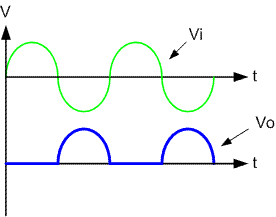
Circuit behavior
Vo = 0 for Vi > 0
Vo = -(R2/R1)Vi for Vi <>
Example waveform

Monday, August 14, 2006

Input Offset Voltage Null Circuit

This circuit is application of OP07. adjust variable resistor for null Offset
Voltage output at initrial state


Op07
Op07 represent a breakthrough in operational amplifier performance.
Low offset and long-term stability are achieved by means of a low-noise,

chopperless, bipolar-input-transistor amplifier circuit. For most applications,

external components are not required for offset nulling and
frequency compensation. The true differential input, with a wide input
voltage range and outstanding common-mode rejection, provides
maximum flexibility and performance in high-noise environments and in

noninverting applications. Low bias currents and extremely high input
impedances are maintained over the entire temperature range.
The OP07 is unsurpassed for low-noise, high-accuracy amplification of
very low-level signals.

Sunday, August 13, 2006

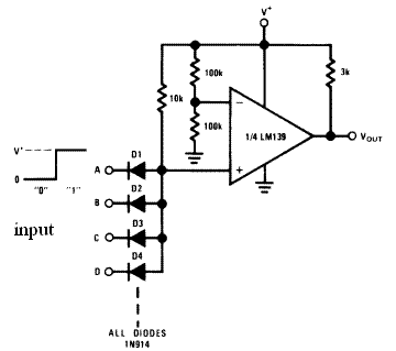
Simple Large Fan-In AND Gate circuit

We can make simple Large Fan-In AND Gate circuit by one Voltage
Comparators from circuit below


Vout = A and B and C and D and ….

This circuit is application of LM139
LM139
Low Power Low Offset Voltage Quad Comparators
The LM139 series consists of four independent precision
voltage comparators with an offset voltage specification as
low as 2 mV max for all four comparators. These were
designed specifically to operate from a single power supply
over a wide range of voltages.

All pins of any unused comparators should be tied to the
negative supply.

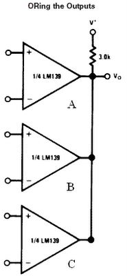
The output of the LM139 series is the uncommitted collector
of a grounded-emitter NPN output transistor. Many collectors
can be tied together to provide an output OR’ing function.


Vo = A or B or C

Thursday, August 10, 2006

On-Off Control With Hysteresis Circuit

We can use inverting Schmitt trigger circuit for this application
Inverting Schmitt trigger
the circuit can be view as an inverting –type threshold detector whose
threshold is controlled by the out put since the output has two stable
state, this threshold has two possible values,namly


Vth = R1*Voh/(R1+R2)
Vtl = R1*Vol/(R1+R2)


The hysteresis width is defined as
Hw = Vth – Vtl = R1*( Voh – Vol )/( R1 + R2 )

Behaviour of circuit show in below picture.


Sample waveforms

Wednesday, August 09, 2006

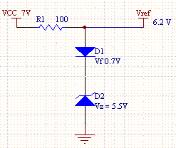
Thermally compensated Zener circuit

Thermal stability is the most demanding performance requirement
Of voltage references

Forward drop of a silicon junction decreases about 2mV for every
degree Celsius increase

The idea behind thermal compensated Zener diode is to connect a
forward-biased diode in series with a Zener diode having an equal
but opposing thermal voltage (TC)


Vref = Vz+Vf = 5.5+0.7 = 6.2 V
Uses Iz = 7.5 mA
R1 = (Vcc-Vref)/Iz = 106.6 ohm

Tuesday, August 08, 2006

Ratiometric Linear Hall Effect Sensors

Hall Effect
If an electric current flows through a conductor in a magnetic field,
the magnetic field exerts a transverse force on the moving charge
carriers which tends to push them to one side of the conductor.
This is most evident in a thin flat conductor as illustrated. A buildup
of charge at the sides of the conductors will balance this magnetic
influence, producing a measurable voltage between the two sides of
the conductor. The presence of this measurable transverse voltage
is called the Hall effect
http://230nsc1.phy-astr.gsu.edu/hbase/magnetic/hall.html

The UGN3503LT, UGN3503U, and UGN3503UA Hall-effect
sensors accurately track extremely small changes in magnetic flux
density—changes generally too small to operate Hall-effect switches.


Each Hall-effect integrated circuit includes a Hall sensing element,
linear amplifier, and emitter-follower output stage. Problems associated
with handling tiny analog signals are minimized by having the Hall cell
and amplifier on a single chip.
Application
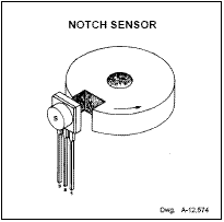
NOTCH SENSOR
The south pole of a magnet is attached to the back of the package if
the Halleffect IC is to sense the presence of ferrous material.

GEAR TOOTH SENSOR
The north pole of a magnet is attached to the back surface if the

integrated circuit is to sense the absence of ferrous matrial.


CURRENT MONITOR
proportional output-voltage levels are dependent on magnetic flux
density at the most sensitive area of the device.

Monday, August 07, 2006

Easy 4-bit magnitude comparator circuit

74HC/HCT85 are easy way for 4-bit magnitude comparator circuit

The 74HC/HCT85 are 4-bit magnitude comparators that can be
expanded to almost any length. They perform comparison of
two 4-bit binary, BCD or other monotonic codes and present the
three possible magnitude results at the outputs (QA>B, QA=B and
QA

FUNCTION TABLE

Saturday, August 05, 2006

C code for 74165

74165 can use for expender input port of microcontroller
74165 are 8-Bit Parallel In/Serial Output Shift Registerswhich shifts data
in the direction of QA toward QH when clocked.Parallel-in access is made
available by eight individual direct datainputs, which are enabled by a low
level at the shift/loadinput. These registers also feature gated clock inputs
and complementary outputs from the eighth bit.
Timing diagram for read data


C code for control 74165 by microcontroller


74165 to microcontroller circuit

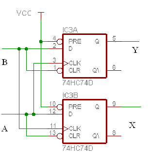
Rotary encoder converter circuit

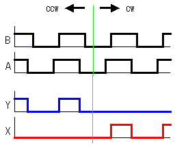
This circuit used convert signal from Rotary encoder (A,B) to two pulse signal
- Y for CCW direction
- X for CW (clockwise) direction
Two pulse signal is easy for microcontroller programing
The circuit used two D-type flip-flop(74HC74D) for the judgement.

Signal input and signal out put

Thursday, August 03, 2006

Converter bridge driver signal circuit

Converter PWM and direction to bridge driver signal circuit
This circuit for convert signal PWM (speed) and signal direction from
microcontroller to signal of motor bridge driver circuit. thay is two pwm
signal A for motor turn right and B for motor turn left

4A DC Motor Drive Circuit , Easy PWM generator circuit